Wilkinson Power Divider Calculator
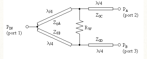
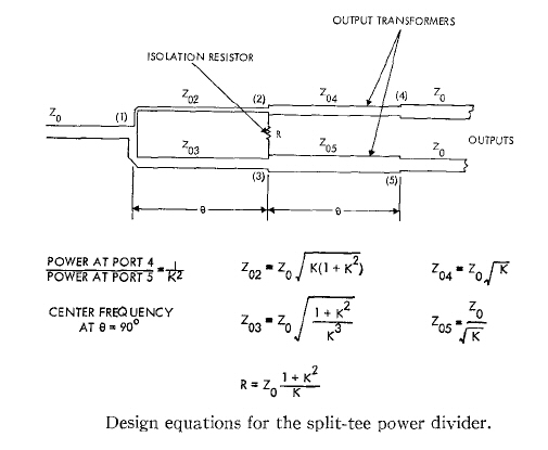
Split Tee Power Divider - the original unequal Wilkinson splitter from 1965. Ideal two-port Wilkinson splitter.
Wilkinson Power Divider Calculator Online Wilkinson Power Divider Calculator App Software Converter Calctown
Chip Resistor De-rating calculator dBmLinear power converter Hybrid Coupler designer LC resonance calculator.
Wilkinson power divider calculator. P p2 Power Output of Port 2. Wilkinson power divider is an N-port passive device 1 however it is commonly found as a 2-way divider 3 ports. Our desire in this case will be unfulfilled.
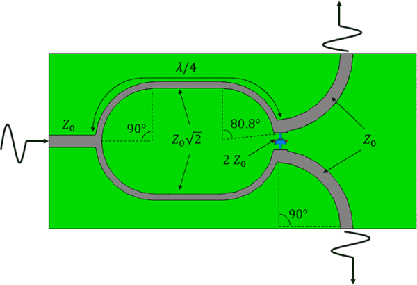
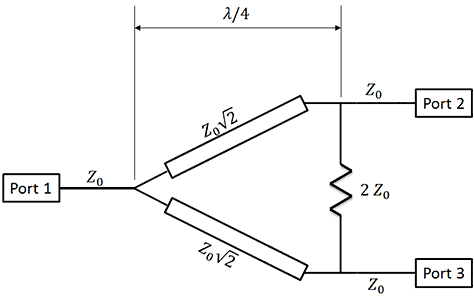
The physical parameters for both the 50 Ω Z 0 and 707 Ω 2 Z 0 can be synthesized using LineCalc. The Wilkinson power divider Wilkinson combiner uses quarter wave transformers to split the input signal to provide two output signals that are in phase with each other. This power divider utilizes a proprietary DLI temperature stable ceramic low loss conductors and integrated resistors.
On Microwave Theory and Techniques vol. Click here to go to our unequal-split power divider calculator it handles Wilkinsons rat-races and branchline couplers. Wilkinson Power Divider Calculator Calculates with the characteristic impedance of the system and ratio of the power at the output to get the impedance of the various transmission lines that make up the Wilkinson Power Divider.
The Wilkinson Power Divider The Wilkinson power divider is a 3-port device with a scattering matrix of. The Wilkinson power divider is a well known device in the RFmicrowave community used for splitting or combining signals. A high ratio Wilkinson power divider is produced by cascading low ratio dividers.
N-Way Power Divider Calculator. Power Combining Problem for Microwave PAs Combining power from various unit PAs is one of the central. Wilkinson Power Divider Calculator.
Wilkinson Power Divider Calculator This CalcTown calculator calculates the parameters related to Wilkinsons power-divider circuit. Potential divider calculator Propagation time calculator Gamma to Impedance converter. A veteran of WWII Mr.
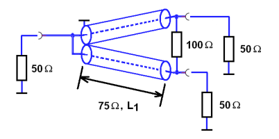
Of EECS The T-Junction Coupler Say we desire a matched and lossless 3-port coupler. Our material on unequal-split Wilkinsons is spread onto the following pages. This paper is to introduce the simple procedure for Wilkinson power divider designing that can be used for both coupled and separated transmission lines.
Wilkinson Power Dividerthe subject of the next section. Wilkinson Power Divider Calculator Enter the characteristic impedance of the system and the ratio of required power at the output to calculate the impedance of the various transmission lines that make up the Wilkinson Power Divider. 4142009 The 3 port Couplerdoc 11 Jim Stiles The Univ.
In the field of microwave engineering and circuit design the Wilkinson Power Divider is a specific class of power divider circuit that can achieve isolation between the output ports while maintaining a matched condition on all ports. Design of Distributed Wilkinson Power Divider 1. In the field of microwave engineering and circuit design the Wilkinson Power Divider is a specific class of power divider circuit that can achieve isolation between the output ports while maintaining a matched condition on all ports.
Combining two 12 and one 13 divider results in a 18 ratio. Theoretically the 18 divider has an S21 of -051dB. Wilkinson power divider splitter combiner circuit.
Z 0 Characteristic Impedance of the Overall System. Bookmark or Favorite this page by pressing CTRL D. The resistor between the two output ports enables the two outputs to matched while also providing isolation.
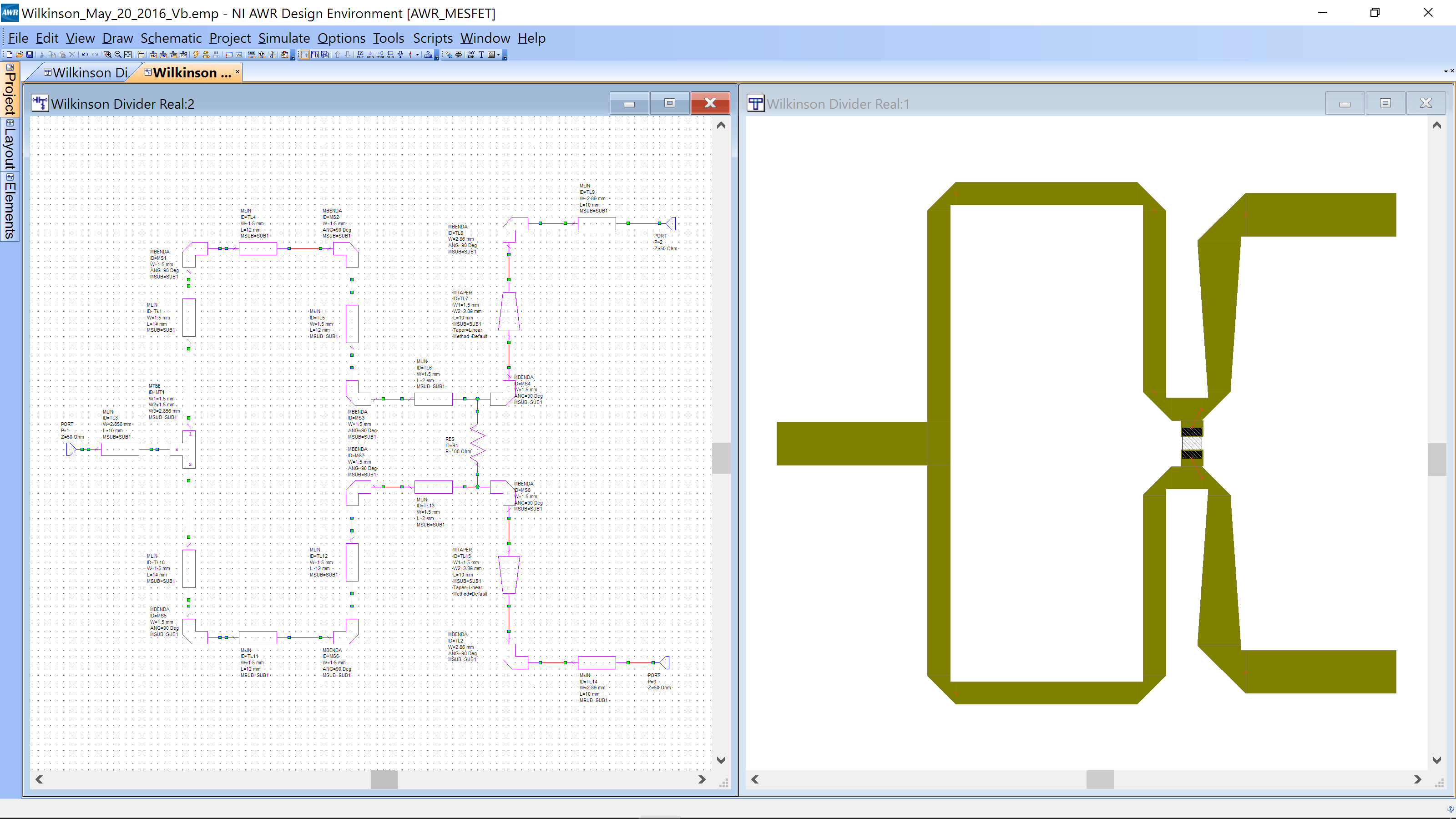
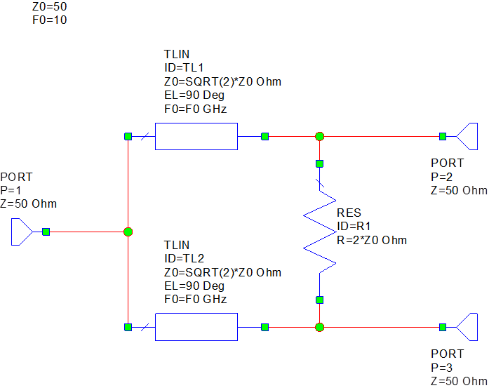
The device provides exceptional performance. Calculate the physical parameters of the Wilkinson Power Divider using the electrical parameters given at the beginning of this chapter. In this notebook we create a Wilkinson power divider which splits an input signal into two equals phase output signals.
Freq 1000MHz to 2000GHz 1000E9 1510E-4. Wilkinson An N-way Power Divider IRE Trans. Smith charts VSWRReturn loss converter Wavelength calculator Wilkinson splitter designer.
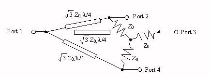
The feeding network was specifically designed for a broadside relatively small linearly-polarized wideband UHF non-scanning array for directed power applications that uses an array radiator with a new. Input power can be split into two or more in phase signals with the same amplitude. Wilkinson Combiner or Divider Short at symmetry plane Open at symmetry plane Odd Mode Even Mode.
Utilizing equal-split stepped-multiple sections of the conventional Wilkinson power divider in microstrip form with a unique topology. Z 1 Z 2 Z 3 Z 4 Network Impedances. Pasternacks N-Way Power Divider Calculator allows you to calculate the total path loss in dB you can expect based on the number of output ports on the RF power splitter device up to 16 ports.
R w Terminating Resistance Between Ports 1 2. P p1 Power Output of Port 1. It is composed of simple transmission lines and a resistor and takes advantage of the properties of quarter-.
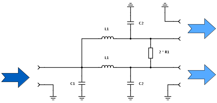
222 SS S 11 21 31 1 Thus just like the lossless divider the incident. Here we will reproduce the ideal circuit illustrated below and discussed in reference 2. 22 2 2 0 00 00 jj j j S Note this device is matched at port 1 S 11 0 and we find that magnitude of column 1 is.
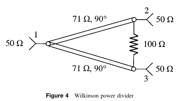
For a two way Wilkinson power divider using λ4 impedance transformer having characteristic impedance 2Z0. By manipulating the S-parameter matrix it can be shown that it is unfeasible to achieve a 3-port device that it is at the same time. Lumped 2-way Wilkinson Splitter Designer Enter the.
Click here to go to our general discussion of Wilkinson power power dividers. The Wilkinson power divider is mentioned as a four port network and even-odd mode analysis is used to calculate the characteristic impedances and resistor values. The results are shown below.
In this example the circuit is designed. The Wilkinson power divider is a basically a three port network that is lossless when the output ports are matched only reflected power is dissipated. The resistor adds no resistive loss to the power split from port 1 so an ideal Wilkinson splitter is 100 efficient.
Reciprocal S ij S ji matched in all the ports S ii 0 lossless S H S I. Theoretical results about this circuit are exposed in reference 1. Wilkinson Power Divider Part number PDW05758 - Overview The Knowles PDW05758 from DLI is a surface mount thin film power divider employing a three section Wilkinson topology.
Wilkinson died on March 10 2012.
Microwaves101 Unequal Split Wilkinsons The Rest Of The Story
Microwaves101 N Way Wilkinson Splitters

630m Wilkinson Power Combiner Amateurradio Com

Wilkinson Power Divider Lumerical Support
Online Calculator Wilkinson Power Split Calculator 3 Port
Wilkinson David S Ricketts

Wilkinson Power Divider Calculator Everything Rf
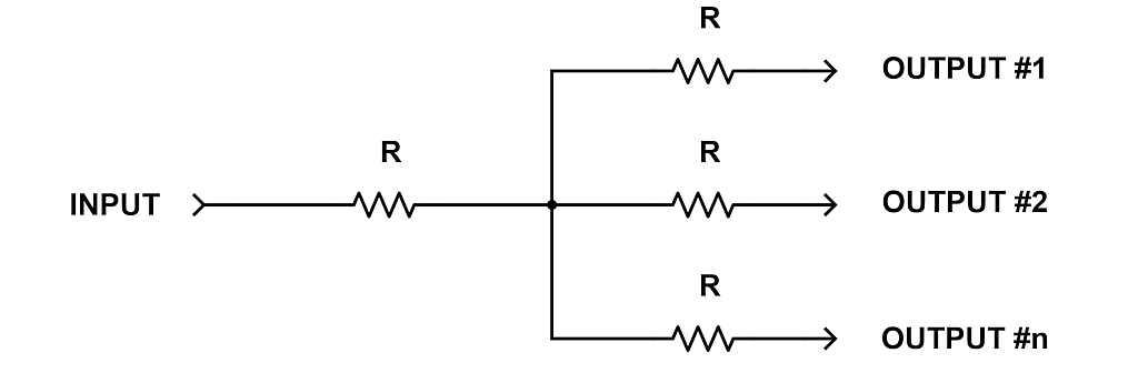
Online Calculator Resistive Equal Power Divider

Wilkinson Power Divider Calculator Everything Rf
Wilkinson Power Divider
Wilkinson Power Divider Scikit Rf Documentation
Wilkinson Power Splitters
Microwaves101 Multistage Wilkinsons

Wilkinson Power Divider Calculator Everything Rf
Wilkinson Power Divider

Wilkinson Power Splitters
Online Calculator Coaxial Power Split

Equivalent Circuit Of The Lumped Wilkinson Power Divider Download Scientific Diagram

Wilkinson Power Divider Download Scientific Diagram
Post a Comment for "Wilkinson Power Divider Calculator"